|
ZVision™ |
ZVision™
A Machine Vision System
for Aircraft Surface Inspection
by
Optical Magnetic Induction (OMI) Imager
0. Introduction
Image processing or analysis involves transformations among several spaces. Image data in the measurement space M need first to be transformed to the feature space F where image properties are represented by a number of features or factors. Then these features are transformed to the decision space D where a decision is made on the interpretation of the scene in an image. Before an image can be transformed to the feature space, preprocessing or filtering operations are needed to clean up the noises (from the imaging system or from other external sources) from the image so that the image data becomes the best possible representation of the scene that has been imaged. A noise-free image is then segmented to identify the AOI (area of interest) using the method based on a fixed or varying threshold.
Segmentation produces a number of AOIs that are used to compute a vector of features for each individual AOI. These features are the attributes that best describe the object of interest in the image. To deal with the imprecise, imperfect and uncertain information at the decision stage of FLIPS, a fuzzy inference engine needs to be developed that mimics human decision-making process in image interpretation. The output of this fuzzy inference engine would help the human operator better understand the material property (crack, corrosion or neither) in the image scanned.
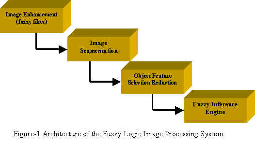
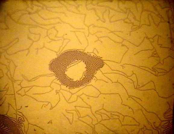
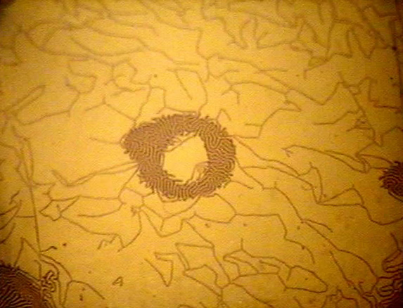
In this project, a Fuzzy Image Processing System (FLIPS), shown in Figure-1, is proposed to automatically recognize cracks around a rivet site (Figure-2 (a)) and material corrosion (Figure-2 (b)) on the surface or sub-surface of the aircraft under OMI inspection. The following four sub-systems have been identified for FLIPS shown in Figure-2 (a) and (b):
1. Image enhancement
2. Image segmentation
3. Feature selection
4. Fuzzy inference engine1. Image Enhancement
Since the digital images are taken by OMI sensors in uncontrolled lighting conditions, there is an uneven lighting across the imaging plane. If not compensated for, a threshold-based segmentation algorithm would fail to pick up the objects of interest, such as the rivet site and cracks, from the original image. In addition, other noises, caused by OMI imaging sensor variation and varying material property, may exist in the digitized images that may affect the performance of image processing algorithms at later stages of the FLIPS. A common method of noise removal is by image filtering. There are many different types of filters, such as digital filters, spatial filters, temporal filters, statistical model-based filters, Kalman filters for time-varying images, median filter and fuzzy filters.
A fuzzy filter is a non-linear filter that performs better than linear filters in most cases. For instance, s non-linear fuzzy filter can be easily implemented to remove the spike noise that exists in many digital images. The filter first computes the local average value of each pixel, Pave, then determine the filter output F by comparing a pixel value at position (x, y) , f(x, y), against the local average Pave, using the following two fuzzy rules: ......
2. Image Segmentation
The purpose of image segmentation is to separate AOI pixels from background pixels (including pixels in the area of no interest) to obtain homogenous object for rivet sites and corrosions.
2.1 Histogram Method
Given the unevenness of the pixel gray level across the imaging plane, a local histogram-based method seems to be an effective algorithm to separate pixels of the rivet site and corrosion from those of the rest. As shown in Figure-3, the histogram of the pixels in a local image window is the probability distribution of pixel gray levels. For the OMI imaging applications, pixels of the rivet site and corrosion usually demonstrate gray levels higher than that of the background. This gives two major peaks in the histogram when the sliding window corresponds to the AOI where there is a rivet site or corrosion area. These two peaks, each presenting a collection of pixels in the image, are separated by the threshold value t that is used to segment the image into a binary image where "1" represents the AOI and "0" the background.
2.3 Fuzzy Segmentation
In addition, the homogeneity of an object in the image is also a fuzzy variable, and concepts (fuzzy sets) such as "very homogeneous," "fairly homogeneous," and "not homogeneous" apply. In principle, a homogeneous object should allow for small difference in pixel values and it should not contain edge pixels (low frequency in the pixel neighborhood). In general, due to noise, image segmentation produces a number of regions that need to be connected or merged to construct an object.
3. Feature Selection
The feature selection problem is characterized by optimization methods that recognize irrelevant and redundant features and suppress them. Irrelevant and redundant features may introduce unwanted noise or make the decision process complicated, degrading the overall system performance. In general, the feature selection process would create a lean model that often generalizes better to new unseen data.
For an imaging system like the OMI sensor, there are a large number of features that can be selected for image analysis purpose. They include
- Physical features – density, scatters, frequency
- Chemical features – atomic number, vapor, material composition
- Statistical features – local and global average and variance, texture attributes
- Geometric features – width, length, all moments, elongation, skewness,
- Positional or relational features – "collinear", "above", "next to"
- Derived features – shape = Width/Length, etc.
- Frequency used by the radiation source of OMI sensor
- Possible inter-frame video information
For automated recognition of rivet sites, we may compute the following features:
- Local average and variance – smooth and uniform
- Elongation
- Inner and outer diameter of the two circles of each rivet site
- Frequency used by the radiation source of OMI sensor
- Background statistics
- Inter-frame video information with static background due to OMI sensor
For corrosion, the following features can be considered:
- Local average and variance – mottled, non-uniform, and non-smooth
- Elongation
- Inner and outer diameter of the two circles of each rivet site
- Frequency used by the radiation source of OMI sensor
- Background statistics
- Inter-frame video information with static background due to OMI sensor
- Edge characteristics (jagged)
4. Fuzzy Inference Engine for Automated Defect Recognition
The purpose of automated defect recognition is to provide an automated tool to aid the human inspector in visually inspect the image. The fuzzy inference engine (an expert system in fact) of FLIPS as shown in Figure-5, converts the input variables from real-world domain into fuzzy numbers, performs fuzzy min/max operations in the fuzzy domain, and converts the resultant fuzzy numbers into real-world values. The output of the inference engine is a vector of output variables (names of the defects) with a possibility value ranging from 0 to 1. An output item (a defect type1) with a high probability value (say 0.96) means that the object under inspection is highly likely to be type1. At the end of operation, it will send out an alarm, either as a buzz sound or as a red flashing light on the screen, when it detects a crack or corrosion area on an image under scanning. The fuzzy inference engine of the FLIPS is developed in three steps:
Defects on Airracrt Surface and Subsurface: original OMI and segmented images
Boeing 767 aircraft and military aircraft body: cracks and corrosions on aluminum (or steel) rivet sites.
Back to Home.